
Vector Network Analyzers (VNAs), also known as vector analyzers, are indispensable in RF testing and characterisation, enabling precise measurement of complex impedance, phase, and amplitude of RF signals. Understanding their practical integration, calibration, measurement techniques, and selection criteria is vital for engineers and technicians working with RF components and systems.
How to Integrate VNAs into Automated Test Equipment and Production Lines
Integrating VNAs into Automated Test Equipment (ATE) and production lines streamlines RF component testing, ensuring high throughput and repeatable measurements. Compact USB VNAs are particularly suited for this purpose due to their portability and ease of connectivity through PC-based software, enabling automation via programmable interfaces such as SCPI commands.
Automation brings benefits like continuous monitoring, reduction of manual errors, and integration with manufacturing execution systems (MES). VNAs can be combined with custom test scripts and plug-ins to orchestrate automated test sequences, allowing real-time pass/fail decisions critical in mass production.
| Integration Feature | Analizador de Redes Vectoriales de Sobremesa Tradicional | USB Vector Network Analyzer (VNA) |
| Tamaño | Large, standalone unit | Compact, USB-connected |
| Costo | Higher initial and maintenance costs | Lower upfront cost with PC-host integration |
| Mobility | Limited | Portable and flexible |
| Control Interface | Manual controls and display | Software-controlled via PC commands |
| Adaptability to Automation | Limited | High, supports scripting and remote control |
| Escalabilidad | Moderado | High, ideal for scalable production setups |
This integration enhances production efficiency while maintaining the accuracy and reliability expected in RF testing.
Best Practices for VNA Calibration: Understanding Vector Error Correction and the 12-Term Model
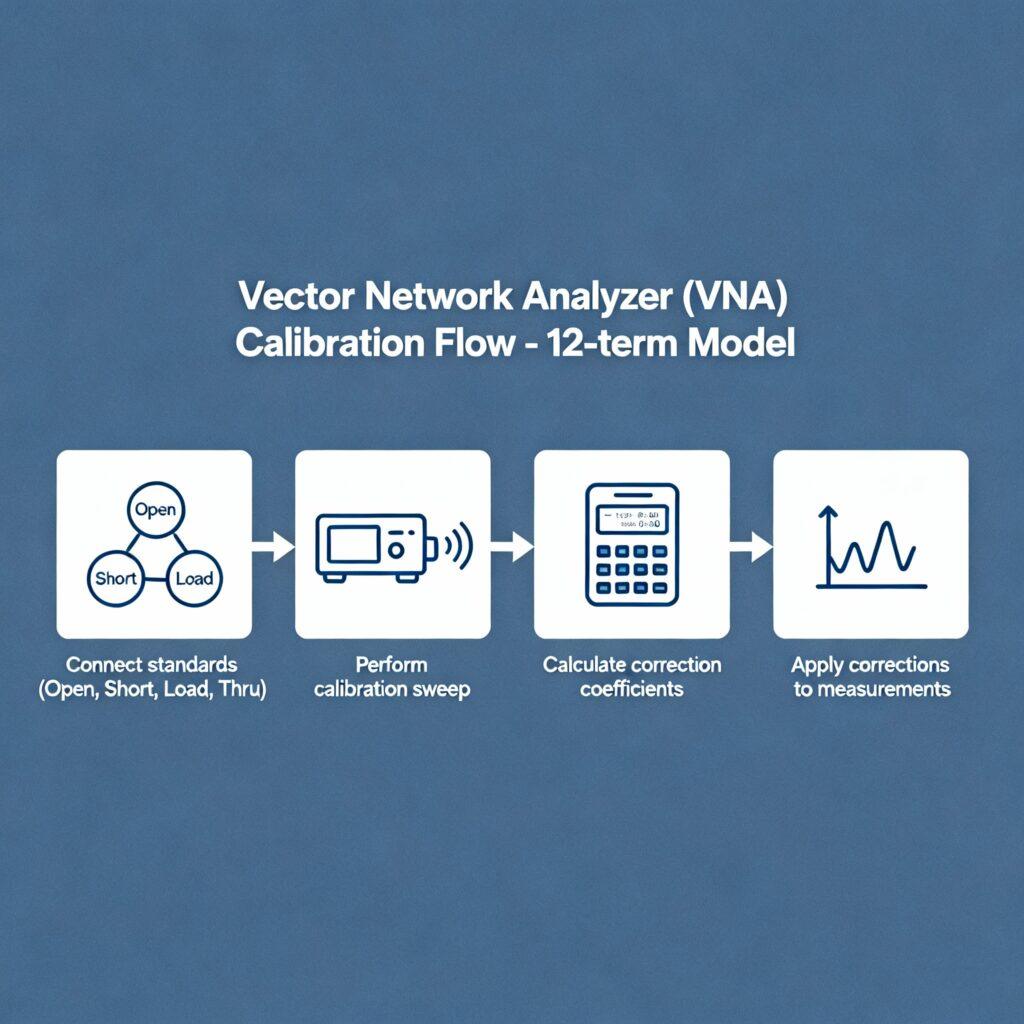
Calibration is essential to correct systematic errors introduced by cables, connectors, and the VNA hardware itself. The 12-term error model is the industry standard for two-port VNA calibrations, addressing errors such as directivity, source/load match, tracking, and crosstalk on both ports.
A typical calibration process uses known standards—open, short, load, and thru (OSLT)—to measure and mathematically remove these error terms through vector error correction, thereby enhancing measurement accuracy.
| Error Term | Descripción |
| Directivity (Ed) | Leakage from source to receiver |
| Source Match (Es) | Mismatches at the source port |
| Load Match (El) | Mismatches at the load port |
| Reflection Tracking (Er) | Gain and phase errors in reflection measurements |
| Transmission Tracking (Et) | Errors in forward transmission measurements |
| Isolation (Ex) | Crosstalk or leakage between test ports |
Proper calibration following the 12-term model is critical to producing high-precision S-parameter results, essential for reliable device characterisation.
Measuring and Interpreting S-Parameters with VNAs for RF Component Characterisation
S-parameters quantify how RF energy is reflected and transmitted through a device, fundamental to characterising components like amplifiers, filters, and antennas. VNAs measure S-parameters across frequencies, yielding complex values that represent magnitude and phase.
Common S-parameters include:
| Parámetro | Descripción | Usage |
| S11 | Input port reflection | Evaluate input impedance and match |
| S21 | Forward transmission gain/loss | Measure gain or attenuation through the device |
| S12 | Reverse transmission | Assess isolation or reverse gain |
| S22 | Output port reflection | Analyze output impedance and matching |
Interpreting these parameters with Smith charts or polar plots helps diagnose impedance mismatches, loss mechanisms, and signal integrity issues, crucial for optimising RF component performance.
Read up on VNAs in Automotive, Aerospace, and Defence
Tips for Selecting the Right VNA for Your Specific Application: Frequency, Dynamic Range, and Ports
Selecting a vector analyzer requires balancing specifications against application needs:
| Specification | Descripción | Recommendation |
| Rango de frecuencia | Operational and harmonic frequencies coverage | Choose based on the highest frequency of DUT plus margin |
| Rango dinámico | Maximum measurable attenuation range | Prefer specification 3-6 dB greater than your device’s losses |
| Number of Ports | Test ports needed for device characterisation | 2 ports for standard devices, more for complex/multi-port DUTs |
| Rastrear ruido | Internal noise affecting measurement accuracy | Lower values (<0.01 dB) are better for sensitive measurements |
| Velocidad de medición | Time per sweep | Higher speed for mass production, less critical for R&D |
High-end VNAs cover frequencies beyond 40 GHz with dynamic ranges exceeding 120 dB and ultra-low trace noise (<0.005 dB RMS). USB VNAs offer portable, cost-effective solutions, especially for frequencies up to 6 GHz, suitable for many applications.
These factors influence test accuracy and efficiency, essential for evolving technologies such as 5G and IoT device testing.
Conclusión
Mastering the use of vector analyzers or VNAs—from integrating into automation, precise calibration with the 12-term model, insightful S-parameter interpretation, to choosing the right instrument—empowers engineers to optimise RF testing and advance product quality.
For cutting-edge VNA solutions tailored to your RF testing needs, Sanko Technologies offers advanced vector analyzers and professional expert guidance. Explore how we can enhance your test capabilities. Ready to elevate your RF testing efficiency and accuracy? Contact our team to discuss personalised solutions for your application and production challenges.