

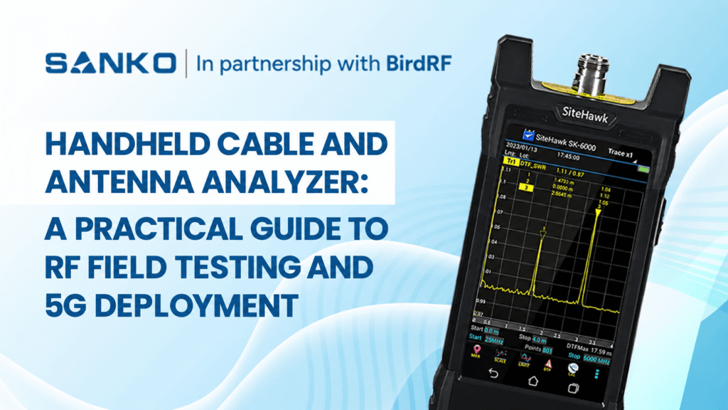
What Is a Handheld Cable and Antenna Analyzer?
A handheld cable and antenna analyzer is a portable field test instrument used by wireless technicians and engineers to measure, verify, and troubleshoot RF (radio frequency) transmission lines and antenna systems.
It checks antenna matching, feedline attenuation and the location of impedance discontinuities. Common measurements include VSWR, return loss, cable loss and distance-to-fault. These measurements support installation, commissioning and maintenance, including 5G antenna testing where accessible passive RF cables and antenna connections need verification.
Why RF Cable Analyzers Are Important for 5G Deployment
A reliable RF connection matters whether technicians are installing a new antenna, checking a jumper cable or investigating deteriorating performance. Loose connectors, damaged feedlines and excessive cable loss can affect the signal path. Testing helps identify problems before technicians replace components unnecessarily.
A handheld cable and antenna analyzer provides information about the connected RF path. Its results help engineers decide whether matching and attenuation meet project requirements and where further inspection is needed.
However, a cable sweep addresses only part of 5G network testing. Coverage, interference, fibre connections, service throughput and active antenna performance require their own measurement methods.
Handheld Advantages in 5G Deployment
The shift toward handheld cable and antenna analyzers reflects practical deployment realities. These instruments combine professional measurement capabilities with field-ready portability, addressing the unique demands of 5G infrastructure installation.
Portable equipment is useful when technicians move between equipment rooms, rooftops and outdoor installations. A practical 5G field testing setup must also include suitable test leads, adapters and calibration accessories.
Battery life, display visibility and environmental protection vary by model. Check the manufacturer’s specifications against actual site conditions rather than assuming every handheld instrument offers the same endurance or ruggedness.
Core Measurements for RF Cable and Antenna Testingnd What They Tell You
| Measurement | What it checks | Practical use |
| VSWR | Impedance matching across frequency | Check whether the measured antenna and feedline system meets its matching specification |
| Return loss | The proportion of the test signal reflected by a mismatch | Assess system matching and compare results with acceptance limits |
| Cable loss | Signal attenuation along the cable | Check whether feedline loss is appropriate for its type, length and frequency |
| Distance-to-fault, or DTF | The distance to impedance discontinuities | Locate suspect connections or cable sections |
| Smith chart and phase, where supported | Detailed impedance and reflection behaviour | Investigate antenna tuning and more complex matching problems |
VSWR: Checking Antenna and Feedline Matching
Voltage Standing Wave Ratio, or VSWR, expresses the matching condition as a ratio. A value closer to 1:1 indicates a better match. Higher values indicate stronger reflections, which may be associated with an unsuitable antenna, damaged connection or other impedance mismatch.
Measure across the required operating band rather than checking only one frequency. An antenna can perform well at one point but fail to meet its specification elsewhere in the band.
Return Loss: Understanding Reflected Power
Return loss describes matching in decibels. When displayed as positive return loss, a higher value indicates less reflected power. For example, 20 dB return loss corresponds to approximately 1% reflected power, while 10 dB corresponds to approximately 10%.
Check the display convention before applying limits. Positive return loss of 15 dB corresponds to S11 log magnitude of approximately −15 dB. Acceptance criteria should follow the equipment specification and project requirements; there is no single return-loss limit that applies to every 4G or 5G installation.
Cable Loss: Checking Feedline Attenuation
Cable loss measures how much signal is attenuated along the transmission line. Compare the result with the expected loss for the cable type, installed length and operating frequency.
Follow the analyzer’s specified measurement procedure. A one-port cable-loss test uses a suitable reflection at the far end, while a two-port transmission measurement requires access to both ends. The connection arrangement and termination must match the selected method.
Distance-to-Fault: Locating Suspect Cable Sections
Distance-to-fault helps technicians identify where reflections occur along the measured RF path. Bird SiteHawk uses frequency-domain reflectometry, or FDR, to produce its fault-location results. This should not be described as identical to the pulse-based method used by every time-domain reflectometer.
A DTF feature identifies an impedance change rather than confirming its cause. Compare the indicated position with known connectors, jumpers and the cable route before deciding what needs inspection.
For further background, read Sanko’s guide to understanding distance-to-fault with a vector network analyzer.
5G Antenna Testing: What Can a Handheld Analyzer Check?
A 5G antenna test may include checking the matching of an accessible passive antenna and its feedline across the required operating band. A handheld analyzer supports this work through return loss, VSWR, cable loss and DTF measurements.
These checks help technicians investigate mismatches, verify passive RF connections and locate suspect feedline sections. The instrument’s frequency range and the installation’s available test interfaces determine which measurements are practical.
However, 5G antenna testing can also include gain, radiation patterns, active antenna performance and beamforming. A connection-based cable analyzer does not independently verify those characteristics.
What Makes Up a 5G Antenna Test System?
A 5G antenna test system should be defined around the required measurements. For passive RF-path checks, the setup may include:
- A cable and antenna analyzer covering the required band.
- A compatible calibration kit.
- A suitable test lead and connector adapters.
- The termination required by the measurement method.
- Cable information and project acceptance limits.
- A method for saving and reporting results.
Additional equipment is needed when the test scope includes radiated performance, interference or other network functions.
Choosing 5G Network Test Equipment
Selecting 5G network test equipment starts with identifying what needs verification. Installation and maintenance teams may need several instruments because matching, interference, fibre condition and service performance are different measurement tasks.
| Testing task | Suitable equipment |
| Passive antenna and feedline matching | Cable and antenna analyzer |
| RF cable attenuation and fault location | Analyzer with suitable cable-loss and DTF functions |
| Interference investigation | Spectrum analyzer with appropriate capabilities |
| Component reflection and transmission | Suitably configured vector network analyzer |
| Passive intermodulation | Appropriate PIM test equipment |
| Fibre-link verification | Optical test equipment suited to the link |
| Coverage and service performance | Task-specific network measurement tools |
| Active antenna and beamforming verification | Appropriate antenna and radio-system test methods |
This helps define a practical 5G test equipment package without assuming one handheld device can complete every acceptance test.
For component measurements, see Sanko’s vector network analyzer guide. For interference-related work, read the guide to choosing a handheld spectrum analyzer.
What Is the Best 5G Network Testing Equipment for Telecom Companies?
The best equipment depends on the operator’s acceptance requirements, operating bands, installation design and field workflow. Begin with the required measurements, then compare instruments and accessories that can perform them under the expected conditions.
Useful selection questions include:
- Does the instrument cover every required test band?
- Are the necessary functions included or separately licensed?
- Can technicians reproduce the required test setup?
- Are suitable calibration accessories available?
- Can results be exported in the required format?
- Does the complete package suit the team’s working conditions?
Some combination instruments offer additional functions through licences or external hardware. Confirm the configuration before comparing quotations. Rohde & Schwarz, for example, identifies separately licensed spectrum and VNA functions for its ZVH platform.

Frequency Coverage: Sub-6 GHz and mmWave Testing
A handheld analyzer must cover the actual frequencies being measured. Supporting several gigahertz does not automatically make an instrument suitable for every 5G band.
Sanko’s SiteHawk product page lists SK4500-TC, SK6000-TC and SK9000-TC models with upper frequency limits of 4.5, 6 and 9 GHz respectively. These limits do not cover 28 or 39 GHz mmWave measurements.
For mmWave work, confirm the frequency range, connectors, calibration accessories and measurement method of the proposed equipment. Also check whether the installation provides an accessible conducted test interface.
Field Testing Best Practices for 5G Installation
Pre-deployment testing should verify performance across the entire operational frequency range, not just at specific design frequencies. This comprehensive approach identifies potential issues before they impact network performance.
A repeatable 5G field testing procedure also defines the calibration reference, cable settings and acceptance criteria.
1. Confirm the Test Requirements
Before connecting the instrument, identify:
- The operating band.
- The cable type and installed route.
- Known connectors and jumpers.
- Required measurements and acceptance limits.
- Cable propagation velocity and loss information.
- The instrument’s RF input restrictions.
Follow the site’s isolation procedure. Do not connect the analyzer’s test port to an energised transmitter feedline. The SiteHawk manual warns against removing an RF transmission line while RF power is present.
2. Inspect the Connections
Inspect the test lead, adapters and accessible system connectors. Damage or contamination in the measurement setup can make a healthy installation appear faulty.
Confirm that accessories are suitable for the operating frequency and connector type. Avoid introducing unnecessary connections into the test path.
3. Calibrate at the Measurement Reference Plane
The reference plane is the connection point where the system being measured begins. When a test lead is used, calibration should account for the lead and adapters between the instrument and that connection.
Follow the model’s calibration procedure. Adding an adapter afterwards can introduce errors that were not included in calibration.
Recheck calibration validity when the frequency range, connections or conditions change. Some instruments support broadband calibration methods that accommodate particular changes; others require recalibration. Follow the exact model’s guidance.
4. Measure and Investigate
Sweep return loss or VSWR across the specified band and compare the results with project limits. Save the trace before changing the setup.
If matching fails, use appropriate cable-loss and DTF measurements to narrow down the problem. Inspect suspect sections, complete repairs and repeat the relevant tests.
5G Network Maintenance Testing
5G network maintenance testing should include comparison with commissioning results where available. Changes in matching, attenuation or DTF traces can help identify deterioration and guide inspection.
Use consistent measurement settings when comparing results. Record the operating band, calibration reference, cable information and connection arrangement so another technician can repeat the test.
| Maintenance observation | Useful next check |
| Matching has deteriorated | Calibration, accessible connections and antenna condition |
| Cable loss has increased | Setup repeatability, expected attenuation and cable condition |
| A DTF feature has changed | Compare its position with known connections and inspect the area |
| Coverage is poor despite a passing sweep | Investigate power, interference and other system conditions |
| Results vary between measurements | Check leads, connectors and calibration validity |
Why Can Good VSWR Still Accompany Poor Coverage?
A passing match does not prove the complete RF path is healthy. Excessive cable attenuation can reduce the signal reaching the antenna.
Loss also attenuates reflections returning to the analyzer, potentially masking a poor antenna match. Review cable loss alongside matching before accepting a reassuring VSWR result.
Why Does the DTF Distance Look Wrong?
DTF distance depends on propagation velocity. An incorrect velocity factor shifts the displayed positions. Mixed cable types and additional jumpers can also complicate comparison with the physical route.
Sweep span affects the ability to separate nearby reflections. Adding data points alone does not automatically improve fault separation. Select settings that cover the cable route while providing useful resolution.
Making the Right Equipment Choice
Selecting the optimal handheld cable and antenna analyzer requires balancing performance requirements, budget constraints, and operational workflows. The most expensive instrument isn’t necessarily the best choice for every application, just as budget options rarely provide adequate capability for professional deployment work.
Consider your team’s experience level when making equipment selections. Advanced analyzers offer impressive capabilities, but they’re only valuable if technicians can effectively utilise their features. Training requirements and learning curves factor into the total cost of ownership equation.
| Selection factor | What to confirm |
|---|---|
| Frequency coverage | Every required test band falls within the model’s range |
| Measurement functions | Required matching, loss and fault-location functions are available |
| Measurement quality | Relevant accuracy, uncertainty and calibration specifications |
| DTF capability | Suitable measurable range and fault resolution |
| Accessories | Compatible leads, adapters, calibration kit and terminations |
| Field operation | Battery, weight, display and environmental limits |
| Documentation | Trace storage and the required export workflow |
| Total cost | Accessories, licences, training and support |
Professional product families include Anritsu Site Master, Bird SiteHawk and Rohde & Schwarz ZVH. Compare exact models and configurations rather than relying on the family name alone.
Recording Results for Site Acceptance
A useful report should allow another engineer to understand and repeat the measurement. Include:
- Site, sector and cable identification.
- Instrument model and configuration.
- Measurement mode and frequency range.
- Calibration reference plane.
- Cable type and DTF settings.
- Applicable acceptance limits.
- Final traces and repair notes.
- Before-and-after results where available.
Use the customer’s required acceptance template where one exists. Consistent records also provide a baseline for future maintenance.
Frequently Asked Questions
Is a Handheld Analyzer a 5G Mobile Network Installation Tester?
A handheld cable and antenna analyzer can form part of a 5G mobile network installation tester setup. It verifies suitable passive RF paths within its frequency range. Complete installation acceptance may also require optical, interference, PIM and service-performance testing.
Can It Identify Water Ingress?
It can reveal changes in reflection or attenuation associated with cable deterioration. DTF helps locate suspect sections, but a trace alone cannot conclusively identify water ingress. Inspection and comparison with earlier results help establish the cause.
Does a Passing Cable Sweep Mean There Is No PIM?
No. Line sweeping and passive intermodulation testing investigate different problems. A connection can pass matching measurements while failing a PIM test. Use appropriate PIM equipment and procedures when that measurement is required.
Can It Verify Antenna Radiation Patterns?
A connection-based matching measurement does not establish radiation patterns, gain or beamforming performance. Those tasks require an appropriate antenna measurement arrangement.
What Information Should I Provide When Requesting a Quote?
Provide the operating bands, cable types and lengths, connector types, required measurements and reporting needs. Mention whether both cable ends are accessible. These details help define a suitable instrument and accessory package.
At Sanko, we understand the importance of selecting equipment around the actual measurement task. Explore our handheld cable and antenna analyzer and share your installation or maintenance requirements through the product enquiry form.
 English
 Chinese
 Korean
 Japanese
 Spanish