

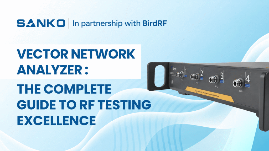
The advancement of radio frequency (RF) technology demands precise measurement instrumentation that must keep pace with increasingly complex communicating systems. Spearheading this progression of technological advancements is the vector network analyzer, which is a high-performance instrument that is now ubiquitous in the latest RF engineering and test applications.
What Is a Vector Network Analyzer?
Vector Network Analyzer (VNA) is a radio frequency (RF) test instrument that measures both the amplitude and phase of high-frequency signals as they reflect from or pass through a device under test (DUT).
It applies a known RF stimulus and measures reflection and transmission as S-parameters, including S11 and S21. Engineers use these results to evaluate antenna matching, filter insertion loss, amplifier gain and cable performance. Accurate measurements require calibration at the DUT connection point.
The advancement of radio frequency (RF) technology demands precise measurement instrumentation that must keep pace with increasingly complex communicating systems. Spearheading this progression of technological advancements is the vector network analyzer, which is a high-performance instrument that is now ubiquitous in the latest RF engineering and test applications.
Understanding Vector Network Analyzers: Beyond Basic RF Measurements
A vector network analyzer measures a device’s complex reflection and transmission response across frequency. Unlike a scalar network analyzer, which measures magnitude, a VNA also measures phase. This information helps engineers assess impedance matching, gain, loss and delay in RF components and systems.
In antennas, communications systems and RF circuits, amplitude and phase relationships help explain component performance. Vector measurements support research and development, production testing and suitable field-service applications, depending on the instrument and test setup.
Today’s network analyzers are well-suited to S-parameter measurement, which describes how electrical networks respond to signals at various frequencies. The measurement is used to characterise passive elements such as filters, couplers, and antennas, as well as active components like amplifiers and mixers.
How Does a Vector Network Analyzer Work?
The VNA generates a controlled signal and sweeps it across a selected frequency range. Directional couplers separate incident, reflected and transmitted waves. Receivers compare these waves with a reference, and the instrument calculates the DUT’s magnitude and phase response.
The process follows four steps:
- Generate a known RF stimulus.
- Apply the stimulus to the DUT.
- Measure incident, reflected and transmitted signals.
- Calculate and display the response across frequency.
Understanding S11, S21, S12 and S22
S-parameters describe how signals reflect from or travel through a device. For a two-port DUT, four main parameters describe matching and transmission in both directions.
| Parameter | Measurement | Typical use |
| S11 | Input reflection | Antenna matching and input return loss |
| S21 | Forward transmission | Filter loss, cable loss and amplifier gain |
| S12 | Reverse transmission | Reverse isolation or transmission |
| S22 | Output reflection | Output matching and return loss |
For a passive filter, S21 shows the transmitted signal across the passband and stopband. S11 shows input reflection. Reviewing both helps distinguish poor matching from other causes of transmission loss.
RF Vector Network Analyzer Applications Across Industries
The RF vector network analyzer has found widespread adoption across multiple industries, each leveraging its unique capabilities for specific applications. In telecommunications, these instruments are essential for designing and testing base station equipment, ensuring optimal signal transmission and reception characteristics. The growing complexity of 5G and emerging 6G technologies has further increased the demand for high-performance RF measurement solutions.
Aerospace and defense applications rely heavily on RF vector network analyzers for radar system development, satellite communication equipment testing, and electronic warfare system characterisation. They are essential for radio frequency (RF) and microwave component analysis of various passive and active devices, including filters, antennas, and power amplifiers.
The automotive industry has become another significant user of RF vector network analyzers, particularly with the advancement of connected vehicle technologies, automotive radar systems, and vehicle-to-everything (V2X) communication protocols. These applications require precise RF component characterisation to ensure reliable performance in challenging automotive environments.
The Rise of USB Vector Network Analyzers: Portable Precision
A USB vector network analyzer uses a connected computer for its interface and measurement control. Professional PC-controlled models can support demanding RF measurements while reducing the space occupied by dedicated instrument displays and controls.
USB connectivity does not determine accuracy, frequency range or suitability. Professional laboratory instruments and hobbyist VNAs can differ considerably. Compare the specifications, calibration capabilities and supported measurements of the particular model.
USB vector network analyzers typically connect to standard personal computers via USB interfaces, leveraging the processing power and display capabilities of modern PCs. This approach reduces instrument costs while providing users with familiar interfaces and extensive data processing capabilities through specialised software applications.
Portability depends on the complete setup, including the computer, power supply, cables and calibration accessories. For outdoor work, check battery operation, environmental limits and ruggedness rather than assuming every USB VNA is field-ready.
Key Advantages of USB Vector Network Analyzers
- Compact size – Saves bench space.
- PC integration – Simplifies viewing and saving results.
- Programmable control – Supports repeated test sequences
- Portable arrangement – Can move between workstations
- Software options – Can enable supported analysis functions
Technical Specifications and Performance Metrics
VNA specifications should be compared under conditions that reflect your application. Dynamic range, trace noise and speed depend on frequency, configuration and measurement settings. A headline figure does not describe performance in every operating condition.
| Specification | Why it matters | What to confirm |
| Frequency range | Defines the bands you can measure | Required start and stop frequencies |
| Port count | Defines available measurement paths | Reflection, transmission or multiport needs |
| Dynamic range | Supports measurement of weak transmission | Performance at the required frequencies and settings |
| Trace noise | Affects small response changes | Specified IF bandwidth and averaging |
| Source power | Sets the stimulus applied to the DUT | Suitable range and adjustment capability |
| Measurement speed | Affects test throughput | Sweep time at the required accuracy |
| Calibration support | Establishes the reference plane | Suitable standards and methods |
IF bandwidth controls part of the receiver’s noise-versus-speed trade-off. A narrower setting can reduce noise but usually increases measurement time. Choose settings based on whether you need fast production screening or detailed component characterisation.
Frequency coverage varies widely among USB and benchtop VNAs. Some professional PC-controlled models reach microwave bands, while others serve lower-frequency applications. Check the datasheet and required options rather than choosing by instrument format alone.
Calibration and Measurement Accuracy
Achieving accurate measurements with any vector network analyzer requires proper calibration procedures that account for systematic errors in the measurement system. A vector network analyzer achieves highly accurate measurements by correcting for the systematic errors in the instrument, the characteristics of cables, adapters and test fixtures.
Standard calibration procedures include Short-Open-Load-Through (SOLT) calibration for coaxial measurements and Through-Reflect-Line (TRL) calibration for specialised applications. Modern instruments often include automated calibration routines that simplify this critical process while ensuring measurement repeatability and accuracy.
Calibration establishes a measurement reference plane. When a cable connects the VNA to the DUT, calibrating at the cable’s end helps account for its effects. Anything added beyond that reference plane can still influence the measured result.
| Calibration approach | Typical application |
| One-port open, short and load | Antenna reflection and input matching |
| Full two-port SOLT | Coaxial reflection and transmission measurements |
| TRL | Suitable fixture, transmission-line or on-wafer testing |
| Electronic calibration | Simplifying calibration with a compatible module |
Calibration reduces systematic errors but cannot eliminate every source of uncertainty. Noise, connector repeatability and changes after calibration can remain. Keep cables stable and use a suitable verification device to check that the setup behaves as expected.
Reassess calibration after changing cables, adapters or the test arrangement. Confirm that calibration standards match the connector type and frequency range. Calibration kits and electronic modules may be separate purchases.
For a deeper explanation, read our guide to practical VNA calibration and measurement techniques.
Vector Network Analyzer Tutorial: Your First Measurement
Begin with a simple task, such as antenna reflection or transmission through a cable. Define the operating band and the result you need before choosing the settings.
- Prepare the setup. Inspect connectors, select suitable cables and follow the manufacturer’s stabilisation guidance.
- Set the sweep. Choose start and stop frequencies covering the DUT’s operating band.
- Select the measurement. Use S11 for input reflection or S21 for forward transmission.
- Set test conditions. Choose appropriate source power, measurement points and IF bandwidth.
- Calibrate. Establish the reference plane at the intended DUT connection point.
- Connect and measure. Keep the calibrated arrangement stable.
- Review and save. Use markers to examine key frequencies and record settings with the results.
For transmission testing, connect the DUT between two test ports. For a simple antenna reflection measurement, connect the antenna at the calibrated port or cable end. Follow instrument and DUT limits, especially when testing active components.
Vector Network Analyzer Antenna Measurement
A VNA measures an antenna’s input reflection to evaluate impedance matching across frequency. Common displays include S11, return loss, VSWR and the Smith chart. Calibrate at the antenna connection point and measure across the intended operating band.
| Measurement | What it tells you |
| S11 | Reflection from the antenna input |
| Return loss | Reflected signal level relative to the incident signal |
| VSWR | Degree of impedance mismatch |
| Smith chart | Resistance and reactance across frequency |
| Impedance bandwidth | Frequency range meeting a defined matching limit |
For a passive antenna, a more negative S11 magnitude in dB means less reflection. Return loss expresses this relationship as a positive value. For example, S11 of −20 dB corresponds to 20 dB return loss.
| S11 magnitude | Return loss | Reflected power | Approximate VSWR |
| −10 dB | 10 dB | 10% | 1.92:1 |
| −15 dB | 15 dB | 3.20% | 1.43:1 |
| −20 dB | 20 dB | 1% | 1.22:1 |
These relationships follow the standard return-loss and VSWR calculations.
Use the antenna or system specification to decide whether a result is acceptable. These values describe matching, not a universal pass/fail threshold.
Good matching alone does not establish antenna gain, radiation pattern or efficiency. An antenna can accept power while losing some of it rather than radiating effectively. Those characteristics require additional measurements and a suitable antenna test arrangement.
The enclosure, mounting position and nearby objects can change antenna impedance. Test under conditions that represent the intended installation and keep the arrangement consistent when comparing results.
Integration with Modern Test Systems
Contemporary RF testing environments increasingly demand instruments that can integrate seamlessly with automated test equipment (ATE) and production line systems. USB vector network analyzers excel in these applications due to their standard computer interfaces and software-based control systems.
Both benchtop and PC-controlled VNAs may support automation. Check the model’s control interface, commands, drivers and software licences. Manufacturing plug-ins and advanced test functions are model-specific rather than standard features of every VNA.
Programming interfaces, including SCPI (Standard Commands for Programmable Instruments) compatibility, allow engineers to develop custom test sequences and integrate vector network analyzer measurements into broader system validation procedures. This programmability extends the utility of these instruments beyond basic measurements to comprehensive system characterisation.
Before automating, establish a repeatable manual measurement and define:
- Calibration and verification procedures.
- Sweep settings, source power and test limits.
- DUT identification and result storage.
- Actions for failed measurements or lost connections.
Comparison with Traditional Benchtop Analyzers
Choose the instrument format around the working environment and required measurements. Benchtop, USB and handheld VNAs can serve professional applications, but their capabilities vary by model.
| Parameter | Benchtop VNA | USB or PC-controlled VNA |
| Interface | Usually integrated display and controls | Host computer and software |
| Bench space | Dedicated instrument footprint | Compact hardware plus computer |
| Performance | Depends on the model and options | Depends on the model and options |
| Portability | Depends on size and power needs | Depends on the complete setup |
| Automation | Available on supported models | Available on supported models |
| Upgrades | Hardware and software options vary | Hardware and software options vary |
Compare total setup cost, supported measurements and specified accuracy. Neither lower cost nor equivalent performance follows automatically from USB connectivity. Software upgrades can enable supported functions but cannot remove fundamental hardware limits.
VNA vs Spectrum Analyzer vs Antenna Analyzer
| Instrument | Main purpose | Example task |
| Vector network analyzer | Measures a DUT’s response to a known stimulus | Filter loss and antenna matching |
| Spectrum analyzer | Examines signal power across frequency | Interference and unwanted emissions |
| Cable and antenna analyzer | Supports installation and maintenance measurements | Feedline matching and fault location |
Some instruments combine these functions. Spectrum analyzers with tracking generators can perform certain response measurements, but phase measurement and calibration capabilities differ. Confirm which functions the instrument supports.
For field-testing considerations, see our guide to handheld spectrum and cable analyzers.
Future Trends and Technological Advances
The vector network analyzer market continues to evolve with advancing technology requirements and emerging applications. Increased frequency coverage, improved dynamic range, and enhanced measurement speed represent ongoing development priorities across the industry.
For buyers, practical developments include wider frequency coverage, multiport testing and stronger software integration. Assess each capability against your project rather than relying on broad claims about future technologies.
Software can expand supported analysis and automation functions. However, frequency coverage, receiver performance and other hardware characteristics still define the instrument’s measurement limits.
How to Choose a High-Frequency Network Analyzer for 6G R&D
Begin with the research band, DUT and required measurement. Different 6G research projects need different systems. A “6G-ready” description alone does not establish suitability.
- Frequency coverage: Confirm calibrated operation across the research band.
- Extension capability: Check whether compatible frequency extenders are required.
- Connections: Assess suitable connectors, waveguides or probes.
- Calibration: Establish the reference plane at the DUT.
- Performance: Check dynamic range and uncertainty at the intended frequencies.
- Measurement scope: Decide whether S-parameters are sufficient or additional instruments are needed.
Advanced component testing may involve a VNA, frequency extenders, controllers and signal-generation hardware. Evaluate the complete measurement system, including calibration and accessories, rather than the analyzer’s maximum frequency alone.
Selecting the Right Vector Network Analyzer for Your Application
Choosing an appropriate vector network analyzer requires careful consideration of several key factors, including frequency range requirements, dynamic range specifications, port configurations, and budget constraints. The decision between traditional benchtop and USB-based solutions depends largely on specific application requirements and operational constraints.
For field testing, assess battery operation, ruggedness and the full setup’s portability. For laboratory and production work, prioritise measurement performance, repeatability and automation. A USB VNA can be suitable when its specifications and working arrangement match these requirements.
Educational institutions increasingly favour USB vector network analyzers due to their combination of professional-grade performance and accessible pricing. These instruments provide students with hands-on experience using the same measurement principles employed in professional RF engineering while fitting within typical educational budgets.
| Application | Requirements to assess |
| Antenna matching | Operating band, reflection accuracy and one-port calibration |
| Cable and filter testing | Two-port capability, transmission accuracy and dynamic range |
| Amplifier testing | Source power, receiver limits and supported active-device functions |
| PCB components | Fixtures, calibration access and de-embedding |
| Multiport devices | Port count, switching arrangement and calibration workflow |
| Production testing | Speed, repeatability and programmable control |
Include calibration standards, suitable cables, adapters, software and any host computer in the quotation. Confirm which functions are included and which require additional licences or hardware.
For devices with several signal paths, explore multi-port and multi-band VNA measurements. For fixture-connected DUTs, read about VNA fixture simulation and de-embedding.
Common VNA Measurement Problems
Unexpected results can come from the DUT, test arrangement or settings. Check the setup before deciding that a component has failed.
- Trace changes when a cable moves – Cable stability, connector condition and calibration validity
- Results differ after reconnection – Connection repeatability and connector handling
- PCB component shows unexpected loss Fixture effects and reference-plane placement
- Noisy measurement trace IF bandwidth, averaging and received signal level
- Good antenna matching but poor range Feedline loss, radiation performance and interference
- Deep filter rejection reaches a flat floor Noise floor, leakage and available dynamic range
Where supported, time-domain analysis can help locate cable discontinuities. Distance-to-fault results also depend on settings such as cable velocity factor. Read our guide to distance-to-fault testing with a VNA.
Sanko: Your Trusted Partner in RF Testing Solutions
When it comes to sourcing high-quality vector network analyzers and RF testing equipment, we are a reliable partner for engineers and organisations worldwide. Our comprehensive product portfolio includes both traditional benchtop and cutting-edge USB vector network analyzers from leading manufacturers, ensuring that our customers have access to the most advanced measurement technologies available.
We understand that successful RF projects depend on accurate measurements and reliable instrumentation. Our technical experts work closely with customers to identify the optimal vector network analyzer solutions for their specific applications, whether in research laboratories, production facilities, or field testing environments.
Our commitment extends beyond product sales to include comprehensive technical support, calibration services, and training programs that help customers maximise their investment in RF test equipment. This holistic approach ensures that our customers can achieve their measurement objectives efficiently and accurately.
Frequently Asked Questions
Is an RF Network Analyzer the Same as a VNA?
An RF network analyzer is a broader description. A vector network analyzer measures magnitude and phase, while a scalar network analyzer measures magnitude. Check the supported measurements when comparing equipment.
Can a USB Vector Network Analyzer Replace a Benchtop VNA?
It can when its frequency coverage, accuracy, ports and measurement functions meet the application. USB describes the connection and working arrangement. Compare specific models and complete setups before choosing.
Can a VNA Locate a Fault in a Cable?
Some VNAs support time-domain or distance-to-fault measurements. These functions use reflection data to help locate discontinuities. Availability and setup requirements depend on the instrument and installed options.
Does Good Antenna Matching Guarantee Good Performance?
No. Return loss and VSWR describe matching, but do not establish gain, radiation efficiency or coverage. Additional testing may be necessary to assess the antenna’s overall performance.
What Information Should I Provide When Requesting a VNA Quotation?
Provide the DUT type, operating frequencies, required ports, measurements, accuracy needs and expected test volume. Include the working environment and existing accessories. This helps identify suitable vector network analyzer solutions and equipment for a complete setup.
Transform Your RF Testing Capabilities Today
The landscape of RF engineering continues to evolve at an unprecedented pace, driven by advancing wireless technologies, increasing frequency requirements, and growing performance demands. Whether you’re developing next-generation communication systems, designing precision RF components, or maintaining critical wireless infrastructure, the right vector network analyzer can make the difference between success and struggle in your projects.
Don’t let outdated measurement equipment hold back your innovation potential. Explore our comprehensive selection of vector network analyzers, from compact USB solutions perfect for field testing to high-performance systems designed for the most demanding applications. Our expert team is ready to help you identify the ideal measurement solution that matches your technical requirements, budget constraints, and performance objectives.
Ready to revolutionise your RF testing capabilities? Contact us today to discover how our cutting-edge vector network analyzer solutions can accelerate your projects, improve your measurements, and give you the competitive edge you need in today’s fast-paced RF marketplace. Your next breakthrough is just a measurement away.
 English
 Chinese
 Korean
 Japanese
 Spanish