

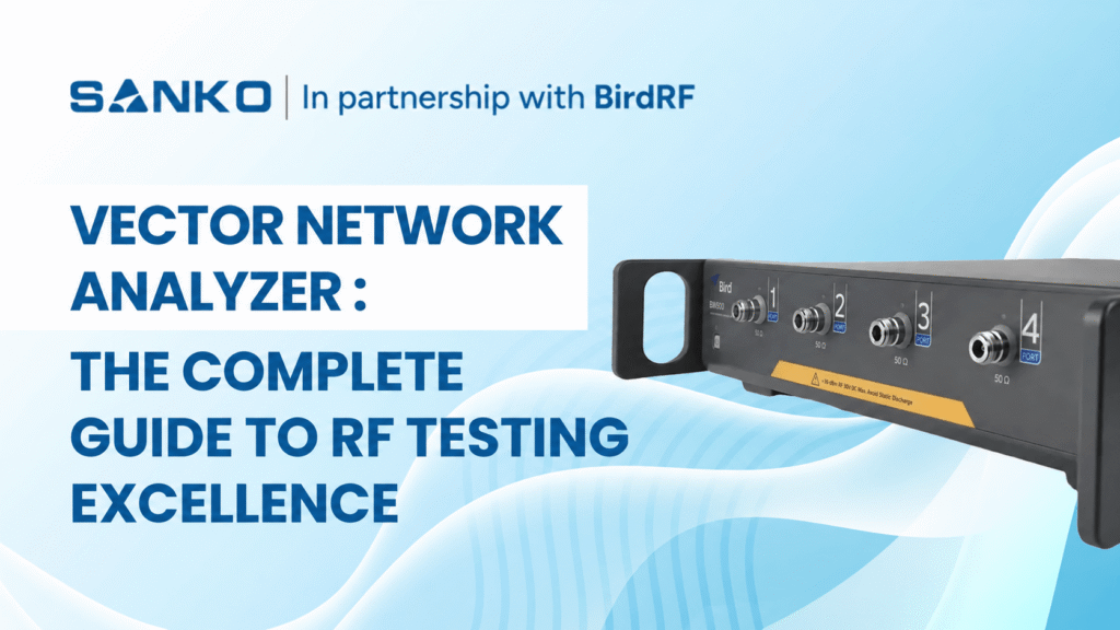
無線周波数(RF)技術の進歩は、ますます複雑化する通信システムに対応できる精密な測定機器を必要としています。この技術革新を牽引しているのがベクトルネットワークアナライザであり、これは高性能な機器で、最新のRFエンジニアリングおよびテスト用途で広く使用されています
ベクトルネットワークアナライザとは何ですか?
Vector Network Analyzer (VNA) is a radio frequency (RF) test instrument that measures both the amplitude and phase of high-frequency signals as they reflect from or pass through a device under test (DUT).
It applies a known RF stimulus and measures reflection and transmission as S-parameters, including S11 and S21. Engineers use these results to evaluate antenna matching, filter insertion loss, amplifier gain and cable performance. Accurate measurements require calibration at the DUT connection point.
無線周波数(RF)技術の進歩は、ますます複雑化する通信システムに対応できる精密な測定機器を必要としています。この技術革新を牽引しているのがベクトルネットワークアナライザであり、これは高性能な機器で、最新のRFエンジニアリングおよびテスト用途で広く使用されています
ベクトルネットワークアナライザの理解:基本的なRF測定を超えて
A vector network analyzer measures a device’s complex reflection and transmission response across frequency. Unlike a scalar network analyzer, which measures magnitude, a VNA also measures phase. This information helps engineers assess impedance matching, gain, loss and delay in RF components and systems.
In antennas, communications systems and RF circuits, amplitude and phase relationships help explain component performance. Vector measurements support research and development, production testing and suitable field-service applications, depending on the instrument and test setup.
今日のネットワークアナライザはSパラメータ測定に非常に適しており、これは電気ネットワークがさまざまな周波数の信号にどのように反応するかを示します。この測定は、フィルタ、カプラー、アンテナなどの受動素子だけでなく、アンプやミキサーなどの能動素子の特性評価にも使用されます。
How Does a Vector Network Analyzer Work?
The VNA generates a controlled signal and sweeps it across a selected frequency range. Directional couplers separate incident, reflected and transmitted waves. Receivers compare these waves with a reference, and the instrument calculates the DUT’s magnitude and phase response.
The process follows four steps:
- Generate a known RF stimulus.
- Apply the stimulus to the DUT.
- Measure incident, reflected and transmitted signals.
- Calculate and display the response across frequency.
Understanding S11, S21, S12 and S22
S-parameters describe how signals reflect from or travel through a device. For a two-port DUT, four main parameters describe matching and transmission in both directions.
| パラメータ | Measurement | Typical use |
| S11 | Input reflection | Antenna matching and input return loss |
| S21 | Forward transmission | Filter loss, cable loss and amplifier gain |
| S12 | 逆送信 | Reverse isolation or transmission |
| S22 | Output reflection | Output matching and return loss |
For a passive filter, S21 shows the transmitted signal across the passband and stopband. S11 shows input reflection. Reviewing both helps distinguish poor matching from other causes of transmission loss.
RFベクトルネットワークアナライザの産業別応用
RFベクトルネットワークアナライザは複数の産業で広く採用されており、それぞれの分野で独自の機能を特定の用途に活用しています。通信分野では、これらの機器は基地局機器の設計および試験に不可欠であり、最適な信号伝送および受信特性を保証します。5Gおよび新興の6G技術の複雑性が増すことで、高性能RF測定ソリューションの需要がさらに高まっています
航空宇宙および防衛用途は、レーダーシステムの開発、衛星通信機器の試験、電子戦システムの特性評価のためにRFベクトルネットワークアナライザに大きく依存しています。これらは、フィルター、アンテナ、パワーアンプを含むさまざまな受動・能動デバイスの高周波(RF)およびマイクロ波部品の解析に不可欠です。
The automotive industry has become another significant user of RF vector network analyzers, particularly with the advancement of connected vehicle technologies, automotive radar systems, and vehicle-to-everything (V2X) communication protocols. These applications require precise RF component characterisation to ensure reliable performance in challenging automotive environments.
USBベクトルネットワークアナライザーの台頭:携帯型の高精度
A USB vector network analyzer uses a connected computer for its interface and measurement control. Professional PC-controlled models can support demanding RF measurements while reducing the space occupied by dedicated instrument displays and controls.
USB connectivity does not determine accuracy, frequency range or suitability. Professional laboratory instruments and hobbyist VNAs can differ considerably. Compare the specifications, calibration capabilities and supported measurements of the particular model.
USBベクトルネットワークアナライザは通常、USBインターフェースを介して標準的なパーソナルコンピュータに接続し、最新のPCの処理能力と表示機能を活用します。この方法により、機器のコストを削減しつつ、専門的なソフトウェアアプリケーションを通じてユーザーに馴染みのあるインターフェースと広範なデータ処理機能を提供します。
Portability depends on the complete setup, including the computer, power supply, cables and calibration accessories. For outdoor work, check battery operation, environmental limits and ruggedness rather than assuming every USB VNA is field-ready.
USBベクトルネットワークアナライザの主な利点
- Compact size – Saves bench space.
- PC integration – Simplifies viewing and saving results.
- Programmable control – Supports repeated test sequences
- Portable arrangement – Can move between workstations
- Software options – Can enable supported analysis functions
技術仕様と性能指標
VNA specifications should be compared under conditions that reflect your application. Dynamic range, trace noise and speed depend on frequency, configuration and measurement settings. A headline figure does not describe performance in every operating condition.
| 仕様 | Why it matters | What to confirm |
| 周波数範囲 | Defines the bands you can measure | Required start and stop frequencies |
| Port count | Defines available measurement paths | Reflection, transmission or multiport needs |
| ダイナミックレンジ | Supports measurement of weak transmission | Performance at the required frequencies and settings |
| Trace noise | Affects small response changes | Specified IF bandwidth and averaging |
| Source power | Sets the stimulus applied to the DUT | Suitable range and adjustment capability |
| 測定速度 | Affects test throughput | Sweep time at the required accuracy |
| Calibration support | Establishes the reference plane | Suitable standards and methods |
IF bandwidth controls part of the receiver’s noise-versus-speed trade-off. A narrower setting can reduce noise but usually increases measurement time. Choose settings based on whether you need fast production screening or detailed component characterisation.
Frequency coverage varies widely among USB and benchtop VNAs. Some professional PC-controlled models reach microwave bands, while others serve lower-frequency applications. Check the datasheet and required options rather than choosing by instrument format alone.
校正と測定精度
あらゆるベクトルネットワークアナライザで正確な測定を行うには、測定システムの系統誤差を考慮した適切なキャリブレーション手順が必要です。ベクトルネットワークアナライザは、機器、ケーブル、アダプタ、およびテストフィクスチャの系統誤差を補正することで、高精度な測定を実現します。
標準的なキャリブレーション手順には、同軸測定のためのショート-オープン-ロード-スルー(SOLT)キャリブレーションと、特殊な用途向けのスルー-リフレクト-ライン(TRL)キャリブレーションが含まれます。最新の機器には、この重要なプロセスを簡素化し、測定の再現性と精度を確保する自動キャリブレーションルーチンが搭載されていることが多いです。
Calibration establishes a measurement reference plane. When a cable connects the VNA to the DUT, calibrating at the cable’s end helps account for its effects. Anything added beyond that reference plane can still influence the measured result.
| Calibration approach | Typical application |
| One-port open, short and load | Antenna reflection and input matching |
| Full two-port SOLT | Coaxial reflection and transmission measurements |
| TRL | Suitable fixture, transmission-line or on-wafer testing |
| Electronic calibration | Simplifying calibration with a compatible module |
Calibration reduces systematic errors but cannot eliminate every source of uncertainty. Noise, connector repeatability and changes after calibration can remain. Keep cables stable and use a suitable verification device to check that the setup behaves as expected.
Reassess calibration after changing cables, adapters or the test arrangement. Confirm that calibration standards match the connector type and frequency range. Calibration kits and electronic modules may be separate purchases.
For a deeper explanation, read our guide to practical VNA calibration and measurement techniques.
Vector Network Analyzer Tutorial: Your First Measurement
Begin with a simple task, such as antenna reflection or transmission through a cable. Define the operating band and the result you need before choosing the settings.
- Prepare the setup. Inspect connectors, select suitable cables and follow the manufacturer’s stabilisation guidance.
- Set the sweep. Choose start and stop frequencies covering the DUT’s operating band.
- Select the measurement. Use S11 for input reflection or S21 for forward transmission.
- Set test conditions. Choose appropriate source power, measurement points and IF bandwidth.
- Calibrate. Establish the reference plane at the intended DUT connection point.
- Connect and measure. Keep the calibrated arrangement stable.
- Review and save. Use markers to examine key frequencies and record settings with the results.
For transmission testing, connect the DUT between two test ports. For a simple antenna reflection measurement, connect the antenna at the calibrated port or cable end. Follow instrument and DUT limits, especially when testing active components.
Vector Network Analyzer Antenna Measurement
A VNA measures an antenna’s input reflection to evaluate impedance matching across frequency. Common displays include S11, return loss, VSWR and the Smith chart. Calibrate at the antenna connection point and measure across the intended operating band.
| Measurement | What it tells you |
| S11 | Reflection from the antenna input |
| Return loss | Reflected signal level relative to the incident signal |
| VSWR | Degree of impedance mismatch |
| Smith chart | Resistance and reactance across frequency |
| Impedance bandwidth | Frequency range meeting a defined matching limit |
For a passive antenna, a more negative S11 magnitude in dB means less reflection. Return loss expresses this relationship as a positive value. For example, S11 of −20 dB corresponds to 20 dB return loss.
| S11 magnitude | Return loss | Reflected power | Approximate VSWR |
| −10 dB | 10 dB | 10% | 1.92:1 |
| −15 dB | 15 dB | 3.20% | 1.43:1 |
| −20 dB | 20 dB | 1% | 1.22:1 |
These relationships follow the standard return-loss and VSWR calculations.
Use the antenna or system specification to decide whether a result is acceptable. These values describe matching, not a universal pass/fail threshold.
Good matching alone does not establish antenna gain, radiation pattern or efficiency. An antenna can accept power while losing some of it rather than radiating effectively. Those characteristics require additional measurements and a suitable antenna test arrangement.
The enclosure, mounting position and nearby objects can change antenna impedance. Test under conditions that represent the intended installation and keep the arrangement consistent when comparing results.
最新のテストシステムとの統合
現代のRFテスト環境では、自動試験装置(ATE)や生産ラインシステムとシームレスに統合できる機器がますます求められています。USBベクトルネットワークアナライザーは、標準的なコンピュータインターフェースとソフトウェアベースの制御システムにより、これらの用途で優れた性能を発揮します。
Both benchtop and PC-controlled VNAs may support automation. Check the model’s control interface, commands, drivers and software licences. Manufacturing plug-ins and advanced test functions are model-specific rather than standard features of every VNA.
プログラミングインターフェースは、SCPI(プログラマブル器機の標準コマンド)互換性を含み、エンジニアがカスタムテストシーケンスを開発し、ベクトルネットワークアナライザの測定をより広範なシステム検証手順に統合できるようにします。このプログラマビリティにより、これらの機器の用途は基本的な測定を超え、包括的なシステム特性評価へと拡大します。
Before automating, establish a repeatable manual measurement and define:
- Calibration and verification procedures.
- Sweep settings, source power and test limits.
- DUT identification and result storage.
- Actions for failed measurements or lost connections.
従来のベンチトップ分析装置との比較
Choose the instrument format around the working environment and required measurements. Benchtop, USB and handheld VNAs can serve professional applications, but their capabilities vary by model.
| パラメータ | Benchtop VNA | USB or PC-controlled VNA |
| インターフェース | Usually integrated display and controls | Host computer and software |
| Bench space | Dedicated instrument footprint | Compact hardware plus computer |
| パフォーマンス | Depends on the model and options | Depends on the model and options |
| 携帯性(けいたいせい) | Depends on size and power needs | Depends on the complete setup |
| Automation | Available on supported models | Available on supported models |
| Upgrades | Hardware and software options vary | Hardware and software options vary |
Compare total setup cost, supported measurements and specified accuracy. Neither lower cost nor equivalent performance follows automatically from USB connectivity. Software upgrades can enable supported functions but cannot remove fundamental hardware limits.
VNA vs Spectrum Analyzer vs Antenna Analyzer
| Instrument | Main purpose | Example task |
| Vector network analyzer | Measures a DUT’s response to a known stimulus | Filter loss and antenna matching |
| Spectrum analyzer | Examines signal power across frequency | Interference and unwanted emissions |
| Cable and antenna analyzer | Supports installation and maintenance measurements | Feedline matching and fault location |
Some instruments combine these functions. Spectrum analyzers with tracking generators can perform certain response measurements, but phase measurement and calibration capabilities differ. Confirm which functions the instrument supports.
For field-testing considerations, see our guide to handheld spectrum and cable analyzers.
未来の動向と技術の進歩
ベクトルネットワークアナライザの市場は、技術要件の進化と新たな応用分野の出現に伴い継続的に発展しています。周波数カバレッジの拡大、ダイナミックレンジの向上、測定速度の強化は業界全体の開発優先事項となっています。
For buyers, practical developments include wider frequency coverage, multiport testing and stronger software integration. Assess each capability against your project rather than relying on broad claims about future technologies.
Software can expand supported analysis and automation functions. However, frequency coverage, receiver performance and other hardware characteristics still define the instrument’s measurement limits.
How to Choose a High-Frequency Network Analyzer for 6G R&D
Begin with the research band, DUT and required measurement. Different 6G research projects need different systems. A “6G-ready” description alone does not establish suitability.
- Frequency coverage: Confirm calibrated operation across the research band.
- Extension capability: Check whether compatible frequency extenders are required.
- Connections: Assess suitable connectors, waveguides or probes.
- Calibration: Establish the reference plane at the DUT.
- Performance: Check dynamic range and uncertainty at the intended frequencies.
- Measurement scope: Decide whether S-parameters are sufficient or additional instruments are needed.
Advanced component testing may involve a VNA, frequency extenders, controllers and signal-generation hardware. Evaluate the complete measurement system, including calibration and accessories, rather than the analyzer’s maximum frequency alone.
アプリケーションに適したベクトルネットワークアナライザの選び方
適切なベクトルネットワークアナライザを選択するには、周波数範囲の要件、ダイナミックレンジの仕様、ポート構成、および予算の制約など、いくつかの重要な要素を慎重に考慮する必要があります。従来のベンチトップ型とUSBベースのソリューションの選択は、主に特定のアプリケーション要件と運用上の制約によります。
For field testing, assess battery operation, ruggedness and the full setup’s portability. For laboratory and production work, prioritise measurement performance, repeatability and automation. A USB VNA can be suitable when its specifications and working arrangement match these requirements.
教育機関は、専門的な性能と手頃な価格を両立するUSBベクトルネットワークアナライザをますます好むようになっています。これらの機器は、学生にプロのRF工学で用いられるのと同じ測定原理を実践的に体験させる一方で、一般的な教育予算内に収まります。
| アプリケーション ( | Requirements to assess |
| Antenna matching | Operating band, reflection accuracy and one-port calibration |
| Cable and filter testing | Two-port capability, transmission accuracy and dynamic range |
| Amplifier testing | Source power, receiver limits and supported active-device functions |
| PCB components | Fixtures, calibration access and de-embedding |
| Multiport devices | Port count, switching arrangement and calibration workflow |
| Production testing | Speed, repeatability and programmable control |
Include calibration standards, suitable cables, adapters, software and any host computer in the quotation. Confirm which functions are included and which require additional licences or hardware.
For devices with several signal paths, explore multi-port and multi-band VNA measurements. For fixture-connected DUTs, read about VNA fixture simulation and de-embedding.
Common VNA Measurement Problems
Unexpected results can come from the DUT, test arrangement or settings. Check the setup before deciding that a component has failed.
- Trace changes when a cable moves – Cable stability, connector condition and calibration validity
- Results differ after reconnection – Connection repeatability and connector handling
- PCB component shows unexpected loss Fixture effects and reference-plane placement
- Noisy measurement trace IF bandwidth, averaging and received signal level
- Good antenna matching but poor range Feedline loss, radiation performance and interference
- Deep filter rejection reaches a flat floor Noise floor, leakage and available dynamic range
Where supported, time-domain analysis can help locate cable discontinuities. Distance-to-fault results also depend on settings such as cable velocity factor. Read our guide to distance-to-fault testing with a VNA.
Sanko:RFテストソリューションにおける信頼できるパートナー
When it comes to sourcing high-quality vector network analyzers and RF testing equipment, we are a reliable partner for engineers and organisations worldwide. Our comprehensive product portfolio includes both traditional benchtop and cutting-edge USB vector network analyzers from leading manufacturers, ensuring that our customers have access to the most advanced measurement technologies available.
私たちは、成功するRFプロジェクトは正確な測定と信頼できる計測機器に依存していることを理解しています。技術専門家は研究所、生産施設、現場でのテスト環境など、お客様の特定の用途に最適なベクトルネットワークアナライザのソリューションを特定するために、お客様と密に連携しています。
私たちの取り組みは製品販売に留まらず、包括的な技術サポート、校正サービス、そしてお客様がRFテスト機器への投資を最大限に活用できるよう支援する研修プログラムを含みます。この総合的なアプローチにより、お客様が効率的かつ正確に測定目標を達成できることを保証します。
よくある質問
Is an RF Network Analyzer the Same as a VNA?
An RF network analyzer is a broader description. A vector network analyzer measures magnitude and phase, while a scalar network analyzer measures magnitude. Check the supported measurements when comparing equipment.
Can a USB Vector Network Analyzer Replace a Benchtop VNA?
It can when its frequency coverage, accuracy, ports and measurement functions meet the application. USB describes the connection and working arrangement. Compare specific models and complete setups before choosing.
Can a VNA Locate a Fault in a Cable?
Some VNAs support time-domain or distance-to-fault measurements. These functions use reflection data to help locate discontinuities. Availability and setup requirements depend on the instrument and installed options.
Does Good Antenna Matching Guarantee Good Performance?
No. Return loss and VSWR describe matching, but do not establish gain, radiation efficiency or coverage. Additional testing may be necessary to assess the antenna’s overall performance.
What Information Should I Provide When Requesting a VNA Quotation?
Provide the DUT type, operating frequencies, required ports, measurements, accuracy needs and expected test volume. Include the working environment and existing accessories. This helps identify suitable vector network analyzer solutions and equipment for a complete setup.
今すぐSankoのRFテスト能力を強化しましょう
RFエンジニアリングの分野は、進化する無線技術、増加する周波数要件、および高まる性能要求により、かつてない速さで変化し続けています。次世代の通信システムを開発する場合でも、精密なRFコンポーネントを設計する場合でも、重要な無線インフラを維持管理する場合でも、適切なベクトルネットワークアナライザがプロジェクトの成功と苦労を分けるポイントとなります。
旧式の測定機器に革新の可能性を妨げられないでください。携帯性に優れたフィールドテスト向けのUSBコンパクトソリューションから、最も要求の厳しい用途向けに設計された高性能システムまで、幅広いベクトルネットワークアナライザをご覧ください。専門チームが、お客様の技術的要件、予算の制約、性能目標に適した理想的な測定ソリューションの特定をサポートいたします。
あなたのRFテスト能力を革新する準備はできていますか? お問い合わせ 当社の最先端 vector network analyzer ソリューションが、プロジェクトの加速、測定の向上、そして急速に進化するRF市場での競争力強化にどのように貢献できるかご紹介します。あなたの次の大きなブレークスルーは、たった一度の測定から始まります。
 Japanese
 English
 Chinese
 Korean
 Spanish